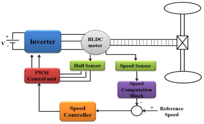
The evolution of electric vehicles (EVs) hinges significantly on the mastery of Brushless DC (BLDC) motor dynamics through mathematical modeling. This understanding is pivotal in developing closed-loop control systems, which are essential for optimizing motor control techniques and ensuring precise management of torque, position, and speed.
In an EV, closed-loop control systems for BLDC motors utilize feedback mechanisms to enhance performance. The aim is to maintain precise control over the motor’s functions, ensuring smooth and efficient operation of the vehicle. As depicted in Fig. 3, the system operates by continuously adjusting the motor based on sensor feedback.
Various sensors gather crucial data about the motor’s performance. These include position sensors, such as Hall effect sensors, speed sensors, and sometimes temperature sensors. A digital signal processor (DSP) or microcontroller processes this data, acting as the system’s brain. The control system requires a reference input, typically set by the driver or vehicle’s control system, which could be a specific speed, position, or torque. The controller compares the actual motor state with this reference input, calculating an error signal to indicate any discrepancies.
Using a control method like a proportional-integral-derivative (PID) controller, the system processes the error signal and determines adjustments needed for the motor. Control signals are sent to the motor’s power electronics to modify the electrical current in the motor windings, aligning the motor’s speed, position, or torque with the desired reference input. This feedback loop is continuous, allowing real-time adjustments and ensuring the motor operates efficiently and adapts dynamically to changes in load or conditions.
Figure 1 illustrates the operational flow and control interface of a proposed speed control system for BLDC motors in EVs. It details the components, their interactions, and the relevant mathematical models.
Information Flow and Component Interaction
Inverter Stage
The inverter is crucial in converting DC supply to the three-phase AC output required by the BLDC motor. Controlled by PWM signals from the control algorithm, it switches current across motor windings using semiconductor switches like IGBTs or MOSFETs. This switching action is mathematically represented as:
$$\:{V}_{rn}={S}_{r}{V}_{dc},\:{V}_{yn}={S}_{y}{V}_{dc},\:{V}_{bn}={S}_{b}{V}_{dc}$$
(17)
where \(\:{S}_{r}\:,\:{S}_{y}\:,\:{S}_{b}\) represent the switching states and the DC link voltage for each phase.
BLDC Motor Dynamics
The inverter-generated phase currents drive the BLDC motor, with the dynamic voltage equation for each phase given by:
$$\:{V}_{a}={R}_{a}{I}_{a}+{L}_{a}\frac{d{I}_{a}}{dt}+{E}_{a}$$
(18)
Here, Va is the phase voltage, Ra is phase resistance, La is phase inductance, Ia is phase current, and Ea is the back emf. The back emf is expressed as:
$$\:{E}_{a}={K}_{e}{\omega\:}_{m}$$
(19)
where Ke is the back emf constant and \(\:{\omega\:}_{m}\) is the rotor’s angular velocity.
Hall and Speed Sensors
Hall sensors provide crucial rotor position feedback for commutation, while speed sensors measure motor speed by timing Hall sensor signals. These feedback signals are continually monitored to make dynamic adjustments.
Control Algorithm Interface
Speed Controller
The speed error, calculated as the difference between the reference and actual speed, is processed by the speed controller:
$$\:e\left(t\right)=\:{\omega\:}_{ref}-{\omega\:}_{m}$$
(20)
A PID controller applies the following control law to determine the control input:
$$\:u\left(t\right)=\:{K}_{p}e\left(t\right)+{K}_{i}\underset{0}{\overset{t}{\int\:}}e\left(\tau\:\right)d\tau\:+{K}_{d}\frac{de\left(t\right)}{dt}$$
(21)
Where Kp, Ki, and Kd are the proportional, integral, and derivative gains, respectively, and u(t) sets the PWM signals for the inverter.
PWM Control Unit
The PWM control unit translates the control input into duty cycles for inverter switches, generating necessary PWM signals by comparing the control signal with a high-frequency carrier waveform.
Mathematical Model for the BLDC Motor
The motor’s electromagnetic torque, proportional to the phase current, is given by:
$$\:{T}_{e}=\:{K}_{T}{I}_{a}$$
(22)
The equation governing motor load dynamics is:
$$\:{T}_{e}-{T}_{L}=J\frac{d{\omega\:}_{m}}{dt}+B{\omega\:}_{m}$$
(23)
where KT is the torque constant, TL is the load torque, J is the moment of inertia, and B is the damping ratio.
Feedback Loop
The closed-loop system maintains desired motor speed through these key phases:
-
a.
Speed Error Calculation: Comparing measured speed with reference speed to determine error.
-
b.
Control Action: PID controller processes speed error to generate control input.
-
c.
PWM Generation: Control input is converted to PWM signals to power the inverter.
-
d.
Motor Response: Inverter output adjusts phase currents to achieve desired speed.
-
e.
Monitoring: Continuous monitoring of rotor position and speed for precise speed management.
This closed-loop system ensures reliable speed control by adapting to changes in load, supply voltage, and other disturbances.
Let’s explore in detail the speed control mechanisms based on PID and Fuzzy logic controllers.
PID Controller
PID controllers are effective in managing motor speed by utilizing proportional, integral, and derivative components in feedback loops. They handle dynamic changes well, providing reliable and responsive speed control crucial for electric vehicles. Tuning PID parameters is vital for optimizing system responsiveness and performance, maintaining consistent speed control. External factors like temperature and load variations may require ongoing adjustments.
PID controller output is mathematically expressed as:
$$\:u\left(t\right)=\:{k}_{p}e\left(t\right)+{k}_{i}{\int\:}_{0}^{t}e\left(\tau\:\right)d\tau\:+{k}_{d}\frac{de\left(t\right)}{dt}$$
(24)
where \(\:{k}_{p}\), \(\:{k}_{i}\), and \(\:{k}_{d}\) are gains that must be tuned to achieve desired performance using methods such as the Ziegler-Nichols method.
Fuzzy Logic Controller
Integrating BLDC motors with a fuzzy logic controller (FLC) enhances performance, especially in non-linear and unpredictable systems. FLCs employ a rule-based approach, using expert knowledge to convert input variables into control signals, effectively handling load and voltage variations. This approach ensures smooth and precise control, crucial for high-precision applications. FLCs’ adaptability allows optimization under varying conditions, and they can integrate with other techniques for improved stability and response. Figure 2 shows the FLC’s schematic diagram.
FLC operation involves three stages:
-
1.
Fuzzification: Converts precise input data into fuzzy sets, providing flexibility by representing a wide range of input scenarios.
-
2.
Fuzzy Inference: Uses pre-set rules to interpret fuzzy input for decision-making based on past and current conditions.
-
3.
Defuzzification: Converts fuzzy output into actionable control signals, ensuring effective application of control strategies.
FLCs are advantageous for improving stability and efficiency in BLDC motor control systems, especially where precise mathematical modeling is challenging. Their ability to handle uncertainty and adapt to various conditions makes them vital in modern motor control applications.
Original Story at www.nature.com

